CN0566 Quick Start Guide
This is the minimum amount of setup to get the Phaser up and running.
Unboxing / Setup Video
Equipment Required
Hardware
Raspberry Pi 4
5V, 3A, USB-C wall adapter
HB100 microwave source
5V benchtop supply or 3 AAA (or AA) cells for HB100 power
Micro HDMI to HDMI cable (or suitable adapters)
16GB or larger SD card
Tripod
One of the following:
Ethernet cable and DHCP-enabled network with internet access
Wireless network
One of the following:
USB keyboard and mouse, HDMI display (if running locally)
Host computer with SSH client and/or VNC client.
Software
ADI Kuiper Linux image
Other
Wired or Wireless network connection, with access to the internet (for accessing update files from GitHub)
This is the step file for the HB100 holder, with a 1/4-20 thread for a standard camera mount. HB100s can vary from manufacturer to manufacturer, so please do a quick measurement on the one you have, and make any necessary adjustments to the step file.
Alternatively, use one of the other mounting methods described in the quick-start video.
HB100 Holder Step File
Overview Photo
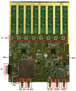
Figure 1 EVAL-CN0566-RPIZ Circuit Evaluation Block assignment
SD card / Software Setup
In order for the Raspberry Pi to control the Phaser devices, you will need to write the ADI Kuiper Linux image to an SD card and configure it. The SD card that ships with the phaser kit MUST be updated with a new image. The Phaser software is tested with Kuiper Linux 2021_R2, which, in spite of the “2021” in the name, was released in Spring, 2023. While there are newer Kuiper Linux releases, this version is required to maintain compatibility with the current phaser software packages.
Download the image from:
Download
2 April 2023 release (2021_r2)
Checksum image_2023-04-02-ADI-Kuiper-full.zip:
0cdcf6e131318113a137cf54335b9614Checksum 2023-04-02-ADI-Kuiper-full.img:
aeff476b577b45cc6ce6ce02403a57c2
Complete instructions for how to write it to the SD card and how to configure an example system are provided at Analog Devices Kuiper Linux.
Hints: The Kuiper Linux wiki pages give a few options, but the “official” Raspberry Pi imager is very straightforward:
Todo
Switch to ADI Kuiper Imager once it’s stable and documented on the wiki.
After writing the image, if a window pops up saying “this card needs to be formatted, would you like to format it now?”, the answer is NO. Eject the card and insert it into the Raspberry Pi’s SD card slot.
Assembling, Booting, and Configuring the System
Connect ADALM-Pluto’s CENTER micro-USB port to Raspberry Pi via micro-USB to USB cable.
CAREFULLY thread the tripod into the tripod mount. Please minimize stress on the tripod mount while plugging in cables and other operations, as it is screwed directly to the PC board.
Verify that the SD card is properly inserted into the slot on the Raspberry Pi.
EITHER:
Connect an HDMI display, USB keyboard, and USB mouse to the Raspberry pi, OR
For remote login, connect the Raspberry Pi’s Ethernet jack to your wired network, or directly to a host computer’s Ethernet jack
Power up the setup through the type-C port of the CN0566. Do NOT connect a supply to the Raspberry Pi.
Wait for Raspberry Pi to boot. (This may take a minute or two, as the filesystem is expanded on first boot.)
After booting, if you are using a keyboard and local display open a terminal as seen on the taskbar. If you are logging in over the network connection,
You can open a graphical desktop VNC session or command line SSH session to hostname analog.local
Configuring the SD Card
The easiest way to configure the SD card is by running a setup script. This does require a wired or wireless internet connection, but it is much easier than doing things manually. A wired connection is fairly straightforward if your network supports DHCP. If you need to use a wireless connection, you’ll have to boot to the graphical desktop and connect manually.
Once connected to a network, run the following commands (and take a look at the setup script if you’re suspicious, and note that there may be some updates as newer versions of Kuiper Linux are released.) The script is commented if you want a detailed description of what it’s doing.
wget https://github.com/thorenscientific/rpi_setup_stuff/raw/main/phaser/phaser_sdcard_setup.sh
sudo chmod +x phaser_sdcard_setup.sh
./phaser_sdcard_setup.sh
sudo reboot
(Wait for the system to reboot)
Note
After running the script, the hostname will be phaser.local
If you are going to be running scripts and other software directly on the Raspberry Pi, it’s a good idea set a few options using the Raspberry Pi configuration utility. This can be accessed from the Start Menu under Preferences, or by running:
sudo raspi-config
from the command line. Set the locale, keyboard, timezone, and wifi country (if you’ll be connecting to your network by wifi.)
You’ll also need to downgrade the numpy version to fix a compatibility issue with our existing example python scripts:
sudo pip install --force-reinstall numpy==1.22
Software Quick Start
At this point, the GUI can be run from the command line. Power up the HB100 source with either a 3V benchtop power supply or two AA cells and aim it a the phaser antenna. Run the following command to find the HB100 frequency:
cd ~/pyadi-iio/examples/phaser
python phaser_find_hb100.py
Ideally, there should be a single, sharp peak as shown in the figure below.
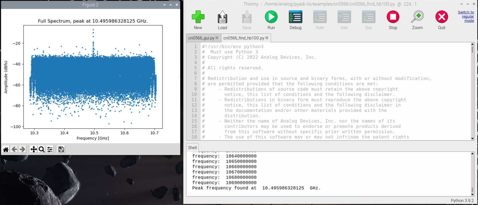
If there is a single prominent peak, enter “y”. If there are several peaks or no visible peak, close the plot and enter ‘n’ at the prompt. Reposition the HB100 (and make sure there are no other sources nearby), then re-run the script.
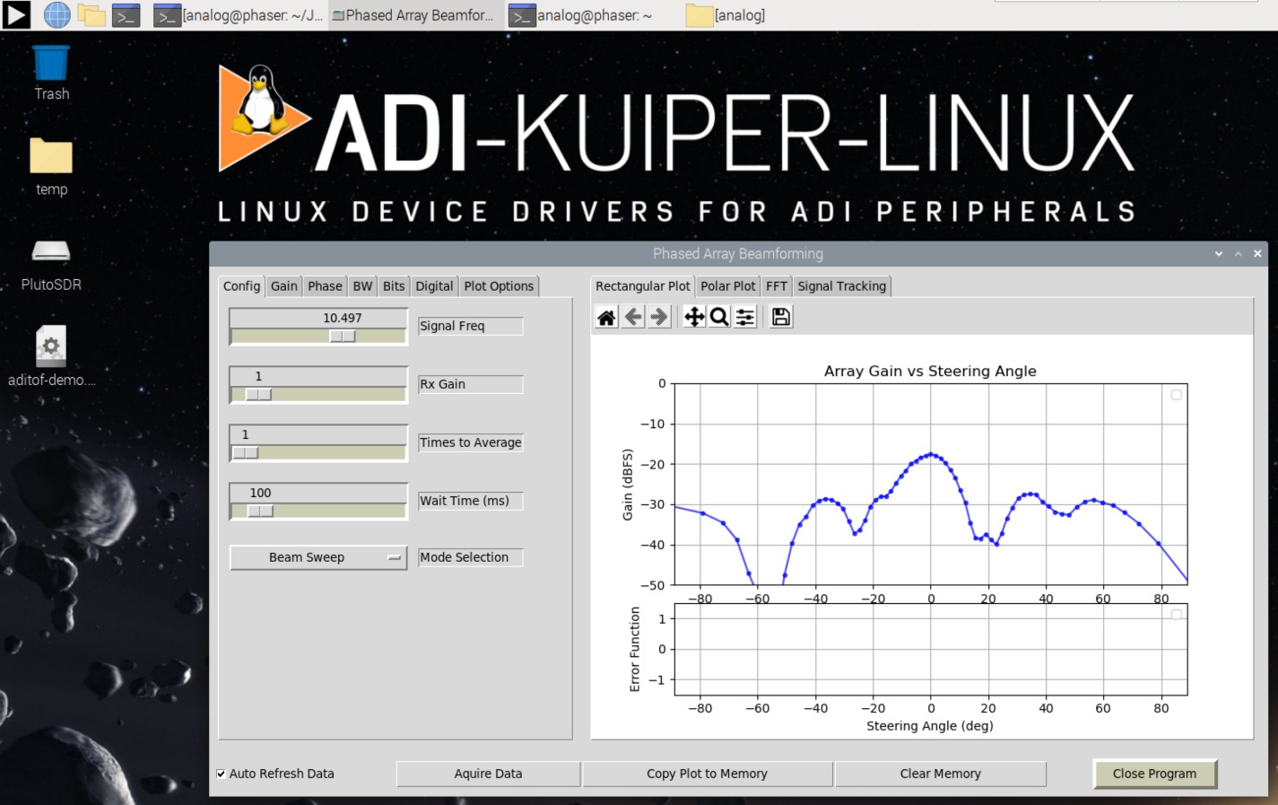
Next run the GUI:
cd ~/pyadi-iio/examples/phaser
python phaser_gui.py
The GUI should load and begin displaying the beam pattern as shown below.
Initial Calibration
The phaser board is initially uncalibrated; each element will have a slightly different gain and slight phase error due to numerous factors. The phaser_examples.py script provides a calibration utility that will generate calibration files. Shut down the GUI if it is running. Place the HB100 directly in front of the array at mechanical boresight , approximately 1.5m away. Then run:
cd ~/pyadi-iio/examples/phaser
python phaser_examples.py cal
The script provides debug information and plots as it is running, you may have to close out of each plot for the script to proceed. After running this script, files gain_cal_val.pkl and phase_cal_val.pkl will be placed in the working directory. The GUI program will also load these files automatically when run again.
Refer to CN0566 Calibration for additional details.
Appendix: Pluto Setup
The Pluto that ships with the phaser kit has been pre-configured. In case something goes wrong, here is how to update the firmware and settings. For the CN0566, the TDD engine and additional control signals are required for some configurations, and were added as of Pluto firmware 0.38. The latest firmware is available from:
The next step is to update the Pluto configuration to enable the AD9361’s second channel. Follow the directions at: Updating to the AD9364,.
For setting the mode of a Rev. C PlutoSDR to 2r2t, the following would be sequence of commands:
fw_setenv attr_name compatible
fw_setenv attr_val ad9361
fw_setenv compatible ad9361
fw_setenv mode 2r2t
reboot
Verify that the configuration was programmed properly by entering the following commands:
fw_printenv attr_name
fw_printenv attr_val
fw_printenv compatible
fw_printenv mode
Which should return:
# fw_printenv attr_name
attr_name=compatible
# fw_printenv attr_val
attr_val=ad9361
# fw_printenv compatible
compatible=ad9361
# fw_printenv mode
mode=2r2t
#
Appendix: Configuration Script Notes
To manually edit config.txt, add the following:
# Phaser board overlay:
dtoverlay=rpi-cn0566

# Heartbeat blinky:
dtparam=act_led_gpio=26
dtparam=act_led_trigger=heartbeat

# Short GPIO121 (Pin 40) to ground for shutdown:
dtoverlay=gpio-shutdown,gpio_pin=21,active_low=1,gpiopull=up
If you will be logging in via VNC, see this article:
Also if running “headless” without a monitor, set the HDMI group and mode accordingly:
# dtoverlay=vc4-kms-v3d

# uncomment to force a specific HDMI mode (this will force 1920x1080)
hdmi_group=2
hdmi_mode=82