CN0566 Hardware User Guide
CN0566 is a phased-array beamforming antenna demonstration platform that allows the user to experience the principles and applications of phased array antennas.
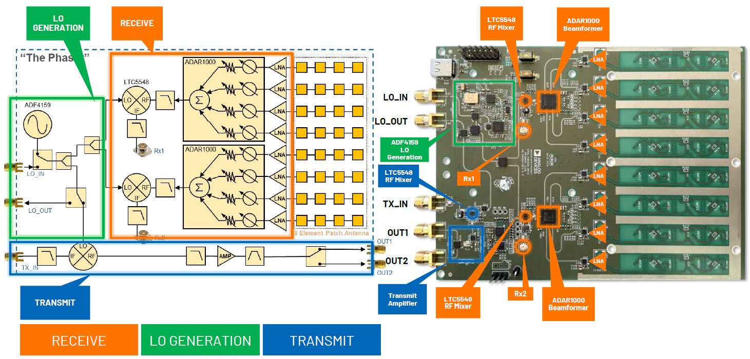
The RF input signal is received from an onboard 8-element patch antenna that operates from 10GHz to 10.5GHz. Each antenna element is input to an ADL8107, a low noise amplifier (LNA) that operates from 6GHz to 18GHz with 1.3dB NF and 24dB gain. The output of these amplifiers is fed into the main core of this circuitry, two of the ADAR1000. The ADAR1000 is an 8GHz to 16GHz, 4-Channel, beamformer that allows per-channel, 360° phase adjustment with 2.8° resolution, and 31dB gain adjustment with 0.5dB resolution. The ADAR1000s are capable of bidirectional, half-duplex operation. However, CN0566 only connects the ADAR1000 receive paths. The outputs of four LNAs get phase and amplitude shifted by an ADAR1000, then summed together at its RFIO output.
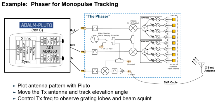
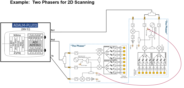
The ADAR1000’s RFIO output passes through a low pass filter before entering the LTC5548 mixer. The low pass filter removes the high side image of the mixer as well as any re-radiation of the high side LO. LTC5548 outputs an IF of approximately 2.2 GHz which passes through a low pass filter (LPF) to remove mixer spurs and attenuate any RF or LO leakage. The LPF’s output, at Rx1 and Rx2, can then be mixed down and sampled by an external 2-channel SDR receiver, such as the ADALM-PLUTO.
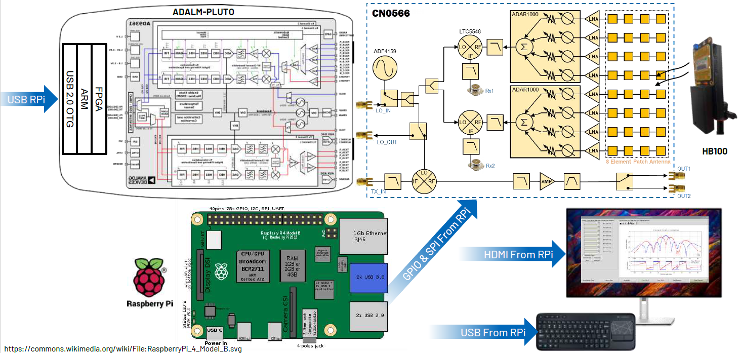
The system consists of the EVAL-CN0566-RPIZ, Raspberry Pi 3 or 4 running ADI Kuiper Linux, an ADALM-Pluto Rev. C, 5V power source, and either keyboard/mouse/monitor OR separate host connected via VNC. The Raspberry Pi 4 provides all SPI, I2C, and discrete digital I/O control signals.
Features
Provides CN0566 software control via Raspberry Pi w/ Kuiper Linux
Includes a 10GHz to 10.5GHz onboard antenna array design but with the option to connect your own antenna
Supports applications running GNU Radio, Python, or MATLAB
Videos
Documents Needed
CN0566 Circuit Note
Equipment Required
Hardware
EVAL-CN0566-RPIZ Board
Raspberry Pi 4
ADALM-PLUTO
5V, 3A, USB-C wall adapter
HB100 microwave source
Micro HDMI to HDMI adaptor
HDMI to HDMI cable
16GB or larger SD card
USB keyboard and mouse
Monitor with HDMI display
Tripod
Software
ADI Kuiper Linux image
Block Assignments
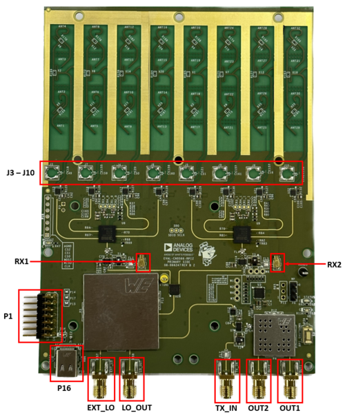
Figure 2 EVAL-CN0566-RPIZ Circuit Evaluation Block Assignment
Connector P1 is the 14-pin header for connection to ADALM-Pluto
Connector P16 is the type C port for the supply
Connector RX1 is the SMA connector for RX1 output
Connector RX2 is the SMA connector for RX2 output
Connector TX_IN is the SMA connector for TX input
Connector TX_OUT_1 is the SMA connector for the first TX output
Connector TX_OUT_2 is the SMA connector for the second TX output
Connector LO_OUT is the SMA connector for the LO output
Connector EXT_LO is the SMA connector for external LO input
Connector J3 to J10 are the footprints for SMP connectors in case an external antenna is to be used
Running the System
Connect ADALM-Pluto to Raspberry Pi via micro-USB to USB cable.
Connect the Raspberry Pi to the monitor via the HDMI cable.
Connect the keyboard and mouse to the USB port of Raspberry Pi.
Follow the Phaser Quick Start Guide here: quickstart
CN0566 Configuration/Setup Examples
More Information and Useful Links
Schematic, PCB Layout, Bill of Materials, Casing
Download
EVAL-CN0566-RPIZ Design & Integration Files
Schematics
PCB Layout
Bill of Materials
Assembly Drawing
Allegro Project